RIDGID MS1065LZ Service Manual
Browse online or download Service Manual for Circular saws RIDGID MS1065LZ. RIDGID MS1065LZ Technical data User Manual
- Page / 67
- Table of contents
- BOOKMARKS
- Power Tools 1
- 1. PRODUCT NAME 4
- 2. MARKETING OBJECTIVE 4
- 3. APPLICATIONS 4
- 4. SELLING POINTS 4
- 5. SPECIFICATIONS 7
- ••••••••••••••• 8
- 3000 or more 13
- Cut-off-side 17
- Saw blade 17
- Fixed-side workpiece 17
- 9. ADJUSTMENT OF COMPONENTS 21
- 10. PACKING 21
- Fig. 32-3 32
- --- 29 32
- Fig. 32-2 32
- --- 31 34
- Fig. 33-4 34
- --- 33 36
- C 10FCE2 USA/CAN 36
- Fig. 35-1 36
- Fig. 35-2 36
- 12. REPAIR GUIDE 44
- Squareness 45
- 0.1/height 45
- Washer (D) 46
- Laser emitting 48
- Work Flow 49
- ELECTRIC TOOL PARTS LIST 51
- C 10FCH2 52
- ALTERNATIVE PARTS --- 3 53
- 10 -- 06 53
- ALTERNATIVE PARTS --- 5 55
- OPTIONAL ACCESSORIES 57
- STANDARD ACCESSORIES 57
- CODE NO 58
- DESCRIPTION REMARKS 58
- C 10FCE2 60
Summary of Contents
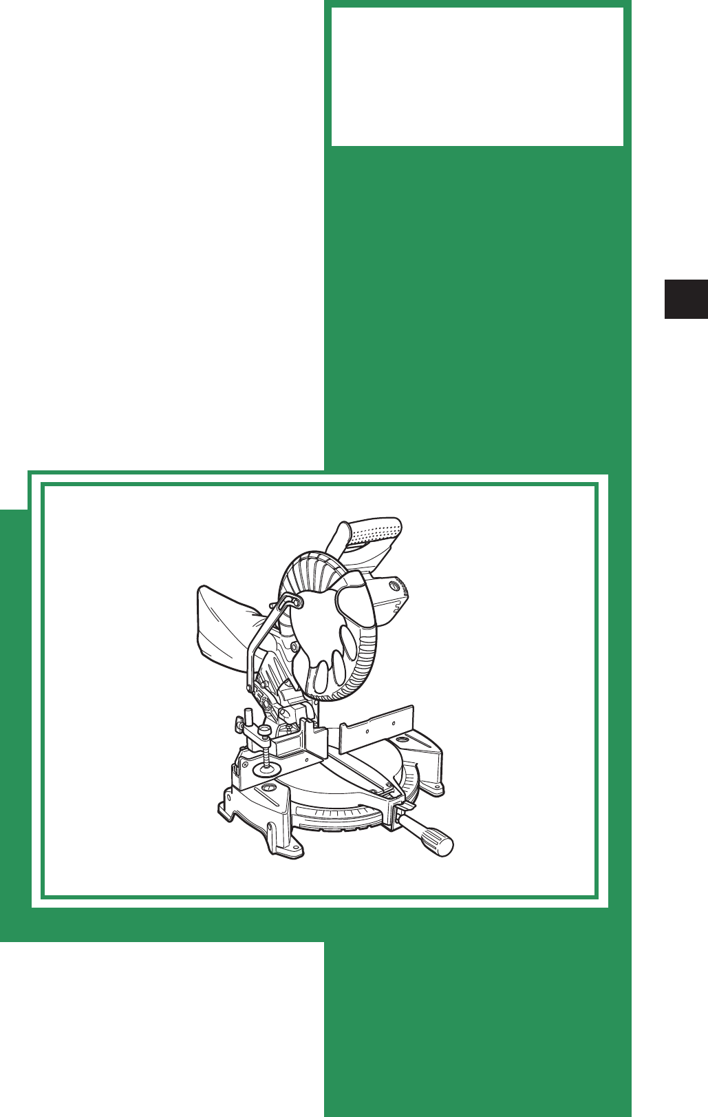
TECHNICAL DATAANDSERVICE MANUALCOMPOUND MITER SAW C 10FCH2C 10FCE2SPECIFICATIONS AND PARTS ARE SUBJECT TO CHANGE FOR IMPROVEMENTLIST No
--- 7 ---7. PRECAUTIONS IN SALES PROMOTIONIn the interest of promoting the safest and most efficient use of the Models C 10FCH2 and C 10FCE2 Compoun
--- 8 ---(2) Caution label (A) (at the front of the hinge) (only the Model C 10FCH2)Do not stare into laser beam. If your eye is exposed directly to
--- 9 ---7-3. Relative StandardsStandards, regulations and guidelines for the safe use of laser equipment[USA] FDA CDRH 21 CFR[AUS/NZL] AS/NZS 2211.
--- 10 ---7-5. Ambient Illuminance and Visibility of Laser Line (Only the Model C 10FCH2)The visibility of the laser line on the workpiece changes d
--- 11 ---Ink lineSaw bladeFig. 7WARNING:Before plugging the power plug into the receptacle, make sure that the main body and the lasermarker are tu
--- 12 ---CAUTION:Laser radiation - Do not stare into beam.Laser radiation on work table. Do not stare into beam. If your eye is exposed directly
--- 13 ---8-3. Confirmation for Use of Sub Fence (B)The Models C 10FCH2 and C 10FCE2 are equipped withsub fence (B). Use sub fence (B) for miter cut
--- 14 ---8-4. Cutting Operation(1) Cutting efficiency will be reduced if a dull saw blade is used, if an excessively long extension cord is used, o
--- 15 ---For miter cut settingIf the turn table has been set to either of the angles described, move the turn table adjusting side handle alittle t
--- 16 ---(1) Setting to cut crown molding at positions and in Fig. 14 (See Fig. 15, tilt the head to the left.):Turn the turn table to th
REMARK:Throughout this TECHNICAL DATA AND SERVICE MANUAL, a symbol(s)is(are) used in the place of company name(s) and model name(s)
--- 17 ---Cutting method of crown molding without tilting the saw blade6 mm wing boltCrown molding stopper (L)(optional accessory)Crown molding stop
--- 18 ---9. ADJUSTMENT OF COMPONENTS9-1. Bevel Angle AdjustmentBefore the power tool is shipped from the factory, it is adjusted for 0û and left 45
--- 19 ---Base packingPacking (D)Packing (F)Fig. 25Fig. 24Packing (F)Carton boxPacking (B)Packing (C)Fig. 26Fig. 23Packing (C)Packing (B)Packing (E)
--- 20 ---11. PRECAUTIONS IN DISASSEMBLY AND REASSEMBLY11-1. Precautions in Disassembly and Reassembly of the Laser Marker (Only the Model C 10FCH2)
--- 21 ---1. Remove the four Bolts M8 x 35 [46], Spring Washers M8 [47] and Bolt Washers M8 [48], then remove Fence(A) [65] and Fence (B) [54].2. Lo
--- 22 ---B. Armature ass'yCord, stator ass'y and housing ass'yTools required: • Phillips screwdriver • Flat-blade screwdriver • Plas
--- 23 ---1. Remove the two Tapping Screws (W/Flange) D4 x 25 (Black) [151] and the four Tapping Screws (W/Flange)D4 x 20 (Black) [152], then remove
--- 24 ---C. Safety cover and linkSpindle and springTools required: • Phillips screwdriver • Hex. bar wrench 4 mm • Hex. bar wrench 3 mm • Box wrenc
--- 25 ---1. Remove the Machine Screw M4 x 8 [131] at the notched side of the Spindle Cover [130] and slide the SpindleCover [130] to remove the TCT
--- 26 ---1. Remove the two Tapping Screws (W/Flange) D4 x 25 (Black) [151] and the four Tapping Screws (W/Flange)D4 x 20 (Black) [152], then remove
PageCONTENTS1. PRODUCT NAME ...
--- 27 ---11-3. ReassemblyReassembly can be accomplished by following the disassembly procedures in reverse. However, specialattention should be gi
--- 28 ---11-4. Wiring DiagramCarefully ensure that wiring is accomplished as illustrated below. As incorrect wiring will result in lack of rotatio
--- 29 ---Fig. 32-2C 10FCH2 Europe (230 V areas)/AUSC 10FCH2 Europe (110 V areas)Fig. 32-3
--- 30 ---Fig. 33-2Fig. 33-1 C 10FCE2 USA/CAN C 10FCE2 Europe (230 V areas)/AUSFig. 33-3 C 10FCE2 Europe (110 V areas)
--- 31 ---Fig. 33-4 C 10FCE2 Asia/South America
--- 32 ---Fig. 34-1 C 10FCH2 USA/CAN2Actual wiring diagram C 10FCH2 Europe/AUS/NZL/China/Hong KongFig. 34-2
--- 33 --- C 10FCE2 USA/CAN C 10FCE2 Europe/AUS/NZL/Asia/South AmericaFig. 35-1Fig. 35-2
--- 34 ---11-5. No-load CurrentAfter no-load operation for 30 minutes, the no-load current values should be as follows.11-6. Reassembly Requiring Ad
--- 35 ---Tolerance0.38/220 (0.016"/8-5/8")0.4/height of fence (0.016"/height of fence)0.1 (0.004")0.4/100 (0.016"/4")
--- 36 ---11-9. Adjustment of Laser Marker Accuracy (Only the Model C 10FCH2)(1) Construction of laser marker and functions of each componentLaser h
--- 1 ---1. PRODUCT NAMEHitachi Compound Miter Saw, Models C 10FCH2 and C 10FCE22. MARKETING OBJECTIVEThe new Models C 10FCH2 and C 10FCE2 are relea
--- 37 ---Hex. bar wrench(2.5 mm)(2) Adjustment of squareness with the fence surfaceThe laser line inclines to the left by turning the hex.socket se
--- 38 ---(4) Adjustment of the laser markerAdjust the laser marker according to the following steps from to .Adjust the product accuracy
--- 39 ---11-10. Tightening Torque(1) Model C 10FCH2• Seal Lock Hex. Socket Set Screw M6 x 10 [3] 43.4 in-lbs. (4.9 N•m, 50 kgf•cm)• Machine Screw (
--- 40 ---(2) Model C 10FCE2• Machine Screw (W/Washers) M6 x 20 (Black) [4] 43.4 in-lbs. (4.9 N•m, 50 kgf•cm)• Machine Screw (W/Sp. Washer) M5 x 16
--- 41 --- a Inaccuratesquareness betweenthe turn table and thesaw blade causes thesaw blade to cut intothe workpiece at anangle. b Excessive defl
--- 42 ---0.1/height of fence(Fig. 50)------------------------ f Inaccurate squarenessbetween the fenceand the turn table and/or the base cau
--- 43 ---• Same as the Item 1- b .• Repair impact marks orscratches on Washer (D) [101]or replace them as necessary.• Same as the Item 1- a .•
--- 44 ---a Excessively fastcutting speedb Core diameter ofextension cord is toosmall.c Excessive cutting forceis applied due to dullsaw blade.d
--- 45 ---a Improper wiringb Switch (A) failurec Switching powersupply failured Laser holder failurea Switching powersupply failureb Laser mo
--- 46 ---13. STANDARD REPAIR TIME (UNIT) SCHEDULESMODEL 10 20 30 406070 min.50FixedVariableC 10FCH2Work FlowSwitch Handle(A)LinkLower Guard (B)Lowe
--- 2 ---4-1. Selling Point Descriptions(1) Laser guide system (Only the Model C 10FCH2)Use the laser marker for aligning with the ink line on thewor
--- 47 ---MODEL 10 20 30 406070 min.50FixedVariableC 10FCE2Work FlowSwitch Handle(A)LinkLower Guard (B)Lower Guard (A)Return SpringSwitchLock LeverH
ELECTRIC TOOL PARTS LISTLIST NO. E945COMPOUND SAWModel C 10FCH22006 • 10 •11(E1) Hitachi Power Tools1345678910111213141516171822233332302526212
--- 2 --- 10 -- 06C 10FCH210010110310110410510610710810911111511211312011812112212311711612412512612812912713013113213313213313413513613714214314414
* ALTERNATIVE PARTS --- 3 ---ITEMNO.CODE NO.DESCRIPTIONREMARKSNO.USEDPARTS10 -- 06C 10FCH21 326-748 LASER HOLDER 1 INCLUD. 22 CAUTION LABEL (A) 13 3
* ALTERNATIVE PARTS--- 4 ---ITEMNO.CODE NO.DESCRIPTION REMARKSNO.USEDPARTS10 -- 06C 10FCH252 949-342 FLAT HD. SCREW M6X25 (10 PCS.) 153 326-704 SUB
* ALTERNATIVE PARTS --- 5 ---ITEMNO.CODE NO.DESCRIPTIONREMARKSNO.USEDPARTS10 -- 06C 10FCH2* 128 877-371 NYLON NUT M5 1 FOR EUROPE* 129 949-236 MACHI
* ALTERNATIVE PARTS--- 6 ---ITEMNO.CODE NO.DESCRIPTION REMARKSNO.USEDPARTS10 -- 06C 10FCH2* 168 360-695F ARMATURE ASS’Y 240V 1 INCLUD. 169-172169 62
OPTIONAL ACCESSORIESITEMNO.CODE NO.DESCRIPTION REMARKSNO.USED* ALTERNATIVE PARTS --- 7 ---10 -- 06STANDARD ACCESSORIESITEMNO.CODE NO.DESCRIPTION REM
--- 8 ---ITEMNO.CODE NO.DESCRIPTION REMARKSNO.USED10 -- 06C 10FCH2Printed in Japan(061011N)
ELECTRIC TOOL PARTS LISTLIST NO. E946COMPOUND SAWModel C 10FCE22006 • 10 •11(E1) Hitachi Power Tools3456789101112131415161822233332302526212728
--- 3 ---(5) Large table for increased material stabilityThe turn table is as large as that of the Model C 10FCH.C 10FCH2/C 10FCE2C 10FCH/C 10FCEOut
--- 2 --- 10 -- 06C 10FCE210010110310110410510610710810911111512011812112212311711612412512612812912713013113213313213313413513613714214314414514614
* ALTERNATIVE PARTS --- 3 ---ITEMNO.CODE NO.DESCRIPTIONREMARKSNO.USEDPARTS10 -- 06C 10FCE2 3 307-956 SEAL LOCK HEX. SOCKET SET SCREW M6X10 1 4 323
* ALTERNATIVE PARTS--- 4 ---ITEMNO.CODE NO.DESCRIPTION REMARKSNO.USEDPARTS10 -- 06C 10FCE255 326-705 HOLDER 156 322-901 LINER (A) 257 322-964 LINER
* ALTERNATIVE PARTS --- 5 ---ITEMNO.CODE NO.DESCRIPTIONREMARKSNO.USEDPARTS10 -- 06C 10FCE2* 134 301-806 WING BOLT M6X15 1 FOR EUROPE* 135 322-950 SP
* ALTERNATIVE PARTS--- 6 ---ITEMNO.CODE NO.DESCRIPTION REMARKSNO.USEDPARTS10 -- 06C 10FCE2* 176 340-686C STATOR ASS’Y 120V 1 INCLUD. 177* 176 340-68
OPTIONAL ACCESSORIESITEMNO.CODE NO.DESCRIPTION REMARKSNO.USED* ALTERNATIVE PARTS --- 7 ---10 -- 06STANDARD ACCESSORIESITEMNO.CODE NO.DESCRIPTION REM
--- 8 ---ITEMNO.CODE NO.DESCRIPTION REMARKSNO.USED10 -- 06C 10FCE2Printed in Japan(061011N)
--- 4 ---No-load rotation speed 5,000 min-1Full-load currentType of motorAC single phase commutator series motor255 mm (10") external dia.5. SPE
--- 5 ---255 mm (10") TCT saw blade (60 teeth, Code No. 976472)••••••••••••••• for normal cutting255 mm (10") TCT saw blade (100 teeth, C
--- 6 ---255 (10")5,0001,5201,950 C 10FCH C10FCE Provided Not provided 1 mWDouble insulation280 (11-1/32")Provided (fixed)250
Related products and manuals for Circular saws RIDGID MS1065LZ
 (16 pages)

 (48 pages)
(6 pages)
(29 pages)
(22 pages)
(6 pages)
(32 pages)
(96 pages)
(33 pages)
(36 pages)
(40 pages)
(36 pages)
(8 pages)
(48 pages)
(6 pages)
(29 pages)
(22 pages)
(6 pages)
(32 pages)
(96 pages)
(33 pages)
(36 pages)
(40 pages)
(36 pages)
(8 pages)
© 2020, manymanuals.com. All rights reserved. | 1.025 s |
 Manymanuals.com
 Manymanuals.de
 Manymanuals.fr
 Manymanuals.it
 Manymanuals.pl
 Manymanuals.cz
 Manymanuals.es
 Manymanuals-pt.com
Comments to this Manuals